Introduction
Here we will present a short and straightforward tutorial to cover the basics of using the general-purpose inputs/outputs (GPIO) on the STM32F4 Discovery using the Keil µVision IDE in the C language. Whilst blinking LEDs may seem basic, the process of setting up the GPIO is instrumental in every future project you undertake with the discovery board. Also, creating your first project and seeing those LEDs flash in front of you is a great motivator!
Firstly, we will set up a Keil project exactly the way which is explained in this tutorial here. We also have to understand a few basics in regards to how the LEDs are connected to the STM32F407VGT6 microcontroller. The four LEDs are connected to pins on the microcontroller and in order to switch them on, the microcontroller must provide a voltage from each respective microcontroller pin. Looking at the STM32F407 Discovery user manual, page 18, (available here) we can see that the LEDs are connected to the following pins:
- Green – Pin 12 of GPIOD
- Orange – Pin 13 of GPIOD
- Red – Pin 14 of GPIOD
- Blue – Pin 15 of GPIOD
Armed with this knowledge, lets make a start on writing some code!
Setting up the LEDs
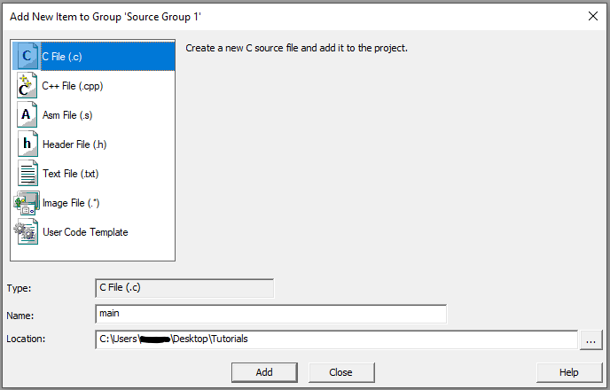
Firstly, create a new main.c file by right clicking the “Source Group 1” and select “Add New Item…”, then selecting the C file template and naming it “main”.

The first line of code that much be included is to tell the compiler where to find some of the functions that will be used throughout this tutorial.
#include "stm32f4xx.h"In a C program, the main executable code goes in the “main” function, defined as:
int main(){
	// Program code goes here
}
Next, the microcontroller pins must be configured in order to turn on the LEDs when commanded. Firstly, all the LED pins are connected to port D of the GPIO and this port must be configured. The GPIOD clock must be enabled (information regarding this can be found in the STM32F407VGT6 processor reference manual if you are interested). The GPIOD clock is enabled using the following code:
RCC->AHB1ENR |= RCC_AHB1ENR_GPIODEN; // Enable the clock of port D of the GPIONow the microcontroller must know is the pins connected to the LEDs outputs and not inputs which is done as follows:
GPIOD->MODER |= GPIO_MODER_MODER12_0; // Green LED, set pin 12 as output
GPIOD->MODER |= GPIO_MODER_MODER13_0; // Orange LED, set pin 13 as output
GPIOD->MODER |= GPIO_MODER_MODER14_0; // Red LED, set pin 14 as output
GPIOD->MODER |= GPIO_MODER_MODER15_0; // Blue LED, set pin 15 as output
The LEDs are now ready to use and the following code implements an infinite while loop (so that the program does not terminate after running a single time).
while(1){
	// Code goes here and is looped infinitely
}
Turning on an LED is done with this code (where X is the pin number):
GPIOD->BSRR = 1<<X; // Set the BSRR bit X to 1 to turn respective LED onSimilarly, turning off an LED is done like so:
GPIOD->BSRR = 1<<(X+16); // Set the BSRR bit X + 16 to 1 to turn respective LED offDelays
Without implementing a delay, the LEDs would turn on and off much too fast for the LEDs to turn on, and would cause them to remain off. A delay can be implemented using a for loop. A variable at the beginning of the “int main()” function must be declared like so:
uint32_t i; // Loop VariableThe for loop is implemented like so:
for(i = 0; i < 1000000; i++){}; // Loop repeats 1,000,000 implementing a delayPutting it all together
The full final code should be along the lines of:
#include "stm32f4xx.h"

int main(){

	// Loop Variables
	uint32_t i;

	// Configue LEDs
	RCC->AHB1ENR |= RCC_AHB1ENR_GPIODEN; // Enable the clock of port D of the GPIO

	GPIOD->MODER |= GPIO_MODER_MODER12_0; // Green LED, set pin 12 as output
	GPIOD->MODER |= GPIO_MODER_MODER13_0; // Orange LED, set pin 13 as output
	GPIOD->MODER |= GPIO_MODER_MODER14_0; // Red LED, set pin 14 as output
	GPIOD->MODER |= GPIO_MODER_MODER15_0; // Blue LED, set pin 15 as output

	while(1){
		// Turn on LEDs
		GPIOD->BSRR = 1<<12; // Set the BSRR bit 12 to 1 to turn respective LED on
		GPIOD->BSRR = 1<<13; // Set the BSRR bit 13 to 1 to turn respective LED on
		GPIOD->BSRR = 1<<14; // Set the BSRR bit 14 to 1 to turn respective LED on
		GPIOD->BSRR = 1<<15; // Set the BSRR bit 15 to 1 to turn respective LED on

		// Delay
		for(i = 0; i < 2000000; i++){}; // Loop repeats 2,000,000 implementing a delay

		// Turn off LEDs
		GPIOD->BSRR = 1<<(12+16); // Set the BSRR bit 12 + 16 to 1 to turn respective LED off
		GPIOD->BSRR = 1<<(13+16); // Set the BSRR bit 13 + 16 to 1 to turn respective LED off
		GPIOD->BSRR = 1<<(14+16); // Set the BSRR bit 14 + 16 to 1 to turn respective LED off
		GPIOD->BSRR = 1<<(15+16); // Set the BSRR bit 15 + 16 to 1 to turn respective LED off

		// Delay
		for(i = 0; i < 2000000; i++){}; // Loop repeats 2,000,000 implementing a delay
	}
}
Building and Downloading the program
With the code complete, the program can now be compiled by using the build button (or the F7 shortcut). Make sure that the STM32F4 Discovery is connected via USB and then Download the program using the Download icon (or the F8 shortcut). The LEDs on your STM32F4 Discovery should now be blinking on and off!
If this project was helpful to you, please check out the other projects or tutorials here.
I try to set up a project for TM4C123, by imitating the way you do for STM. But what showed up on my Keil_v5 is very different, and I couldn’t make it work. Could you point to some sort of tutorials or books? I am an electrical engineering student. I took an intro course for MicroP. The problem is we only focused on how to write assembly and how it gets encoded or decoded. The instructor only gave us all the setup files necessary for the course. Now I want to set up a project myself and try to write in C some programs that involved interrupt. But I failed, I have no clue how to even find the proper header files and C files, and assemble them together.
Any help would be appreciated,
sincerely,
Paul
Hi,
I purchased STM32F4 Discovery microcontroller then I powered it up and by default the LEDs were blinking in turns. Then, I used your code and wrote it into Flash, all of a sudden LEDs were displayed solid and not blinking, Any idea what is wrong?
Thanks,
Afshin