Introduction
The BMP family of sensors from Bosch Sensortec are temperature and pressure sensors that are incredibly small and precise (more information on these sensors can be found here). They have many uses in industrial applications as well as hobbyist arduino projects. However, due to their tiny size, handling these sensors can be challenging for beginners. Thankfully for us, Adafruit make breakout boards with these sensors pre-soldered with all the required supporting components!
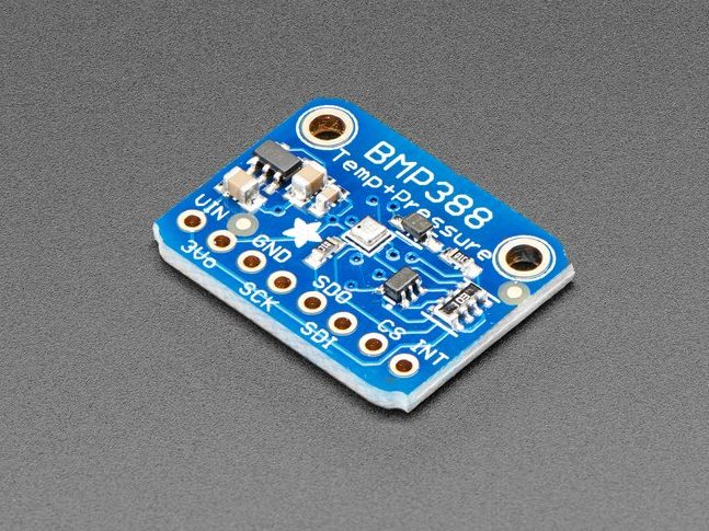
In this tutorial we will use an Adafruit BMP388 Breakout Board which is readily available from many online electronics retailers. The wiring and most of the coding similar across all of the BMPxxx family of sensors and breakout boards, but there may be some slight alterations required. If I end up writing specific tutorials for the other boards then I shall list them right here.

Connecting the BMP388
The Adafruit BMP388 Breakout Board supports both I2C and SPI methods of communication and our Arduino (in this case, a Nano) also supports both. The selection of which protocol to use does not particularly matter when dealing with only one component attached to the Arduino. However, we will use I2C as it is arguably slightly easier to set up.
Firstly, we must connect the board to the Arduino Nano. The I2C protocol requires two lines, SCK and SDI. These are named on the breakout board but are less easy to find on the Nano. By inspecting an Arduino pin-out diagram such as the one below, you can find out which pins correspond to I2C communication.
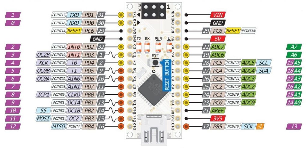
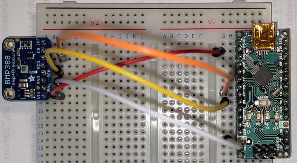
The Nano’s SCL pin (A5) connects to the SDK pin on the breakout board. The Nano’s SDA pin (A4) connects to the breakout’s SDI pin.
Now all that is left is to power the breakout board. Due to the small current draw of the BMP sensor, it can be easily powered by the Nano. Connect the VIN pin on the breakout board to the corresponding 3.3V pin on the Nano. The breakout’s GND pin is connected to the Nano’s GND pin.
Programming the Arduino
With the physical connections complete, we can move onto programming the Arduino! Firstly, open the Arduino IDE and connect the Arduino via USB.
We will need to install two libraries (provided by Adafruit) to make the sensor function correctly. They can both be installed from the Arduino Library Manager. In the Arduino IDE start a new sketch. Click “Sketch” then “Include Library” then “Manage Libraries”. Search for and install the following:
- Adafruit bmp3xx
- Adafruit Unified Sensor
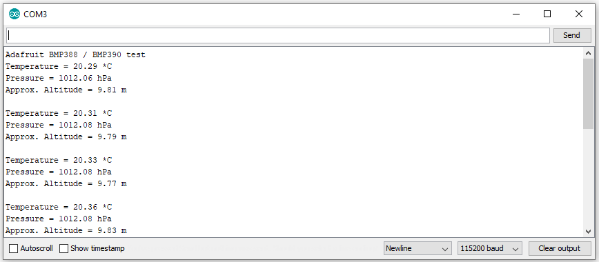
After installing these libraries, an example sketch is made available by Adafruit and can be found under “File” then “Examples” then “Adafruit BMP3XX” then “bmp3xx_simpletest”. This code can be modified to work over I2C by commenting out lines 38 and 39 (adding a double slash “//” before the code). If you compile this code and upload it to your Arduino, you can see your BMP388 sensor in action in the serial monitor (Ctrl + Shift + M). Note, ensure you have set the Baud rate to 115200.
If this tutorial has helped you, please consider checking out our other tutorials and projects which you can find here.