Introduction
In this tutorial we will walk through how to use FreeRTOS SMP on the RP2040. SMP or symmetric multiprocessing will allow us to make use of both of the Arm Cortex M0+ cores in the RP2040 microcontroller whilst using a real time operating system. In this tutorial we will cover how SMP works, how to create a project that will utilise it along with a couple of simple demo projects.
Video Tutorial
Template project repository link
This project is intended as a template for starting other FreeRTOS RP2040 projects. If you would like to directly download the template without following the tutorial then you can clone the directory using the following:
git clone --recurse-submodules https://github.com/LearnEmbeddedSystems/rp2040-freertos-templateChanges to FreeRTOSConfig.h
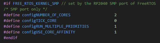
Once you have cloned the git repository, open the folder in VSCode. Open the FreeRTOSConfig.h in the “src” folder and scroll down to line 108. Turn configNUMBER_OF_CORES from 1 to 2. Technically that is all you have to do to turn a single core FreeRTOS program into an SMP multicore one!
Example 1: Blinky Demo
In this demo we simply create two tasks. One will pass a semaphore to the other task every half a second which in turn will blink the LED.
#include <stdio.h>
#include "pico/stdlib.h"
#include "pico/multicore.h"
#include "FreeRTOS.h"
#include "task.h"
#include "semphr.h"

const int task_delay = 500;
const int task_size = 128;

SemaphoreHandle_t toggle_sem;

void vTaskSMP_demo_delay(void *pvParameters){

    for (;;) {
        xSemaphoreGive(toggle_sem);
        vTaskDelay(task_delay);
    }

}

void vTaskSMP_demo_led(void *pvParameters){

    for (;;) {
        if(xSemaphoreTake(toggle_sem, portMAX_DELAY)){
            gpio_put(25, !gpio_get_out_level(25));
        }
    }
}

void main(){
    stdio_init_all();

    gpio_init(25);
    gpio_set_dir(25,1);

    toggle_sem = xSemaphoreCreateBinary();

    xTaskCreate(vTaskSMP_demo_delay, "A", task_size, NULL, 1, NULL);
    xTaskCreate(vTaskSMP_demo_led, "B", task_size, NULL, 1, NULL);
    vTaskStartScheduler();
}
Make sure that your CMakeLists.txt file looks like this:
add_executable(${ProjectName}
    main.c
)

target_include_directories(${ProjectName} PRIVATE
    ${CMAKE_CURRENT_LIST_DIR}
)

target_link_libraries(${ProjectName}
    pico_stdlib
    pico_multicore
    FreeRTOS-Kernel-Heap4
    )

pico_enable_stdio_usb(${ProjectName} 1)
pico_enable_stdio_uart(${ProjectName} 0)

pico_add_extra_outputs(${ProjectName})
Example 2: Core Pinning
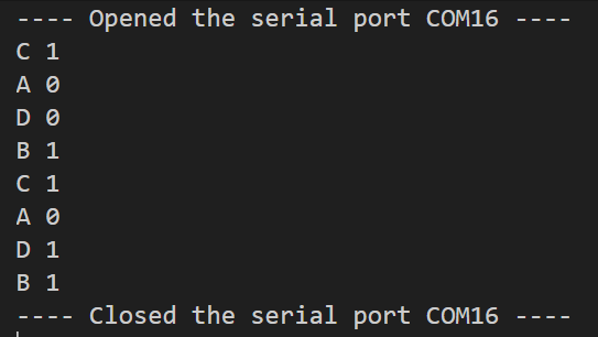
In this example, we spawn 4 cores named A to D. We pin tasks A and B to cores 0 and 1. Then we let the scheduler decide which cores the other tasks should run on.
#include <stdio.h>
#include "pico/stdlib.h"
#include "pico/multicore.h"
#include "FreeRTOS.h"
#include "task.h"
#include "semphr.h"

const int task_delay = 500;
const int task_size = 128;

SemaphoreHandle_t mutex;

void vGuardedPrint(char *out){
    xSemaphoreTake(mutex, portMAX_DELAY);
    puts(out);
    xSemaphoreGive(mutex);
}

void vTaskSMP_print_core(void *pvParameters){
    char *task_name = pcTaskGetName(NULL);
    char out[12];

    for (;;) {
        sprintf(out, "%s %d", task_name, get_core_num());
        vGuardedPrint(out);
        vTaskDelay(task_delay);
    }

}

void main(){
    stdio_init_all();

    mutex = xSemaphoreCreateMutex(); // Create the mutex

    // Define the task handles
    TaskHandle_t handleA;
    TaskHandle_t handleB;

    // Create 4x tasks with different names & 2 with handles
    xTaskCreate(vTaskSMP_print_core, "A", task_size, NULL, 1, &handleA);
    xTaskCreate(vTaskSMP_print_core, "B", task_size, NULL, 1, &handleB);
    xTaskCreate(vTaskSMP_print_core, "C", task_size, NULL, 1, NULL);
    xTaskCreate(vTaskSMP_print_core, "D", task_size, NULL, 1, NULL);

    // Pin Tasks
    vTaskCoreAffinitySet(handleA, (1 << 0)); // Core 0
    vTaskCoreAffinitySet(handleB, (1 << 1)); // Core 1

    // Start the scheduler
    vTaskStartScheduler();
}
Once built and uploaded to the RP2040, open a serial monitor and point it at the COM port of the RP2040. In the output you should see that tasks A and B are pinned to cores 0 and 1 respectively. Tasks C and D should alternate around cores 0 and 1 like so: