This short project covers how to use the serial output over USB on your Raspberry Pi Pico. Below the video you can find the project source code, and below that you can find a written version of the project.
Introduction
Using a serial monitor over USB means that you can essentially output data from your Pico to your PC. It is a very similar process to using the serial monitor on your Arduino.
In this tutorial we are going modify our blink LED code that we made in a previous tutorial. We are going to output a string over USB to further indicate when the LED is on or off. Obviously, you can use the technique we describe here to print to whatever you want in your projects to the serial port.
I am working on a windows machine and so we will need some kind of serial monitor application to monitor the COM port that the Pico will communicate over. I will use PuTTY, and you can download it from their website linked in the description. You can also use the Arduino IDE serial monitor if you have it installed.
Configuring CMakeLists.txt
So lets open Visual Studio code. Open a developer command prompt by using the windows search, then open Visual studio code using the code command. Navigate to the folder where you have stored your project, if you haven’t set one up then follow the tutorial, linked here, which will show you how to set up a project.
The first change we need to do is in the CMakeLists file. We need to tell the compiler that we are going to be using the USB output and to disable the UART output. This is done with the following:
pico_enable_stdio_usb(blink_led 1)
pico_enable_stdio_uart(blink_led 0)
Writing our C file
In our C file, we need to include the stdio header file at the start.
#include <stdio.h>Then the first action we need to do in our main function is to call the following function:
stdio_init_all();Then we can head into our infinite loop. After we turn the LEDs on I want the Pico to send a message over the serial port indicating that the LEDs are on. We do this with the printf function with the string that we want to send, in this case I will simply say LED on. We finish the string in a newline operator so each message is printed on a new line in the serial monitor. I will repeat this after we have turned the LEDs off. I will also increase the delay slightly.
printf("LED ON!\n");The printf function can be used to send a variety of information through the serial output, like variables and so on. It is extensively documented as it is a very common function in C.
Building and Uploading
Now we are ready to build the project, press the build button on the bottom task bar and you should see it build without errors. If you open the build directory with windows explorer you will see the blink led uf2 file we will use to program the board. Lets check to see if the blink LED works as intended! Connect your Pico over usb whilst pressing it’s boot select button. Simply drag and drop the UF2 file over to the Pico’s storage, it will reboot and then start blinking!
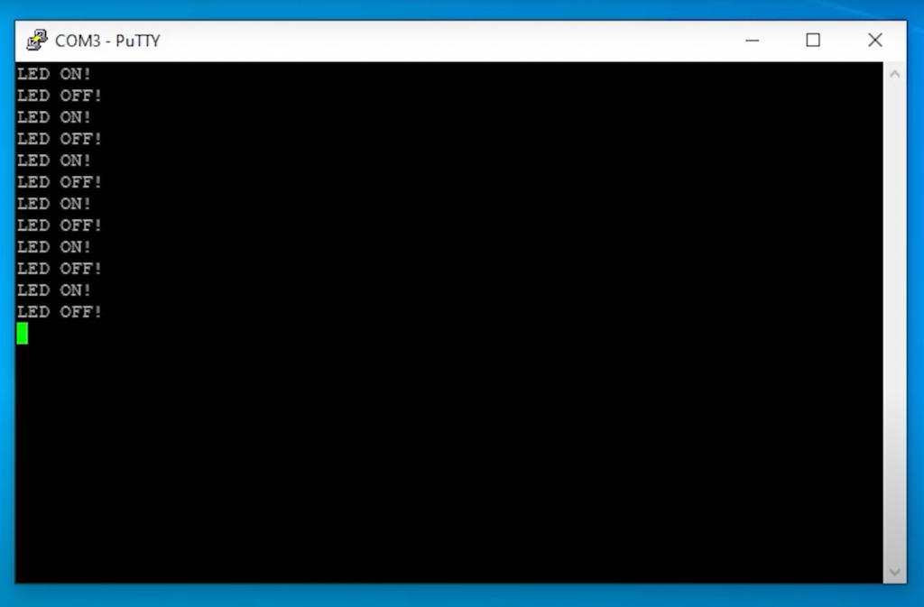
Now open your serial monitor of choice, I will use putty. Now you need to find out which COM port your Pico is connected to. You can simply open device manager then expand the ports section. Select this port in your Putty window with a baud rate of 115,200 and open the monitor. You should now see your output in the window!
Project Source Code
CMakeLists.txt
cmake_minimum_required(VERSION 3.12)

include(pico_sdk_import.cmake)

project(pico-projects)

pico_sdk_init()

add_executable(blink_led
    blink_led.c
)

target_link_libraries(blink_led pico_stdlib)

pico_enable_stdio_usb(blink_led 1)
pico_enable_stdio_uart(blink_led 0)

pico_add_extra_outputs(blink_led)
blink_led.c
#include <stdio.h>
#include "pico/stdlib.h"

int main(){
    //Initialise I/O
    stdio_init_all();

    // initialise GPIO (Green LED connected to pin 25)
    gpio_init(25);
    gpio_set_dir(25, GPIO_OUT);

    //Main Loop
    while(1){
        gpio_put(25, 1); // Set pin 25 to high
        printf("LED ON!\n");
        sleep_ms(1000); // 0.5s delay

        gpio_put(25, 0); // Set pin 25 to low
        printf("LED OFF!\n");
        sleep_ms(1000); // 0.5s delay
    }
}
Thank you – worked like a charm!
Thanks for the example – does exactly what it’s supposed to! I have a related question, though: How to get serial input from the USB port? I want to issue a text command such as “scan i2c” – How can I do it? scanf()/fscanf() functions don’t seem to work; nor do gets()/fgets() (using stdin as the default for the fxxx() functions…)
These functions jam the cpu… Any ideas?
Thanks, this works when you are ok to monitor things in the loop, but what if you want read something during the time program initializes. Putty would not connect until pico is running and and after I connect via putty, messages on serial port are long gone, so I cannot see them …
Robert,
A run/reset button is the solution you need.
The Maker Pi Pico by Cytron has one.
You can also modify the code to accept serial inputs. There’s a demo in the official pico-examples repo named “uart_rx” that shows how to receive input. You’ll need to include that kind of code in a project such as this page’s demo that uses USB instead of UART.
Hope this helps!
getchar(); works for me 🙂
Thank you so much for this!
I have been working with the official pico-examples, but encountering problems migrating some of the UART demos to USB. I decided to simplify everything and create a project from scratch. Your tutorial was very helpful and got me up and running quite quickly!
I can’t connect the pico to my pc, the Device Manager is able to see the device but says that there are no drivers for it. I search online but i did’t found any driver. Any suggestions?