This article (and video) covers the basics of multicore programming on the Pico and hopefully demonstrate why you would want to use both cores of the Pico. The full project source code is available at the bottom of this article.
Introduction
When writing complex projects, where timing is an important aspect of your program, seemingly simple tasks can bog down your microcontroller. In a multi-threaded application, certain tasks can be passed to the second core, freeing up the processor to work on the tasks you want it to do. As an example, one core handles an interface or communication application whilst the other core handles say sensor data acquisition.
How does it work?
I am going to give you a conceptual overview of the system and how it works, this is a an oversimplification but it will give you the basics so you can start developing your own projects.
In the RP2040 Chip, we have two cores, 0 and 1. They both share the same memory which they can communicate with. In single core operation, core zero executes all of the code you have written. However, in a multicore program, core zero starts, then hands a series of executable functions to core one to process in parallel.
In most applications, you will want to communicate between the two cores. In the case of the RP2040, there are two FIFO buffers that can be accessed by the cores. A FIFO buffer is a first in first out buffer, which simply means that the first data written to the buffer is the first data read. One of the buffers can only be written to by one core, through a process called pushing, and read by the other core by a process called popping. You can see that neither core can write to, or read from, more than one buffer. This actually makes our life quite straightforward.
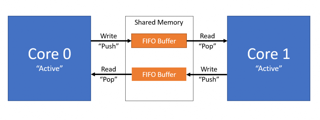
When data is written to the buffer by either one of the cores, an interrupt is triggered in the other core. This signals that data is waiting for it and to tell the interrupt handler to do something with it!
Multicore Programming!
Finally, what you actually came here for! Hopefully, the overview gave you the groundwork of how a multicore microcontroller like the Raspberry Pi Pico. We are going to write a multicore program which uses core 0 to read the on chip temperature sensor on the Pico. This is then sent to core one which will print it over a serial USB connection.
We will create a project as explained in this video tutorial.
Starting with the CMakeLists file we use the standard format and add the following libraries: (Full source code at the end of this article!)
- Pico Standard Libraries
- Pico Multicore
- Hardware ADC
When in the target_link_libraries function it looks like this:
target_link_libraries(multicore
        pico_multicore
        pico_stdlib
        hardware_adc
)
We then enable the USB serial output as explained in this tutorial here.
Now onto our C File. We want to include the following libraries:
#include <stdio.h>
#include "pico/stdlib.h"
#include "pico/multicore.h"
#include "hardware/irq.h"
#include "hardware/adc.h"
Now we write 3 functions:
// Core 1 interrupt Handler
void core1_interrupt_handler() {

}

// Core 1 Main Code
void core1_entry() {

}

// Core 0 Main Code
int main(void){

}
In the main function, we initialise the sdtio and then, begin the core 1 code execution. Then we initialise the ADC and read the temperature sensor at one second intervals. Sending data to core 1 is done with the multicore_fifo_push_blocking function. Our main function now looks like this:
// Core 0 Main Code
int main(void){
    stdio_init_all();

    multicore_launch_core1(core1_entry); // Start core 1 - Do this before any interrupt configuration

    // Configure the ADC
    adc_init();
    adc_set_temp_sensor_enabled(true); // Enable on board temp sensor
    adc_select_input(4);

    // Primary Core 0 Loop
    while (1) {
        uint16_t raw = adc_read();
        multicore_fifo_push_blocking(raw);
        sleep_ms(1000);
    }
}
Now we write the code which will be excecuted on core 1. The interrupt handler will actually be handling the data conversion and sending, so this function simply configures the core 1 interrupt.
// Core 1 Main Code
void core1_entry() {
    // Configure Core 1 Interrupt
    multicore_fifo_clear_irq();
    irq_set_exclusive_handler(SIO_IRQ_PROC1, core1_interrupt_handler);

    irq_set_enabled(SIO_IRQ_PROC1, true);

    // Infinte While Loop to wait for interrupt
    while (1){
        tight_loop_contents();
    }
}
Finally, we have the interrupt handler. The conversion logic performed here can be found in the RP2040 data sheet and information regarding printing over USB can be found in my tutorial here.
// Core 1 interrupt Handler
void core1_interrupt_handler() {
// Receive Raw Value, Convert and Print Temperature Value
while (multicore_fifo_rvalid()){
uint16_t raw = multicore_fifo_pop_blocking();
const float conversion_factor = 3.3f / (1 << 12);
float result = raw * conversion_factor;
float temp = 27 - (result - 0.706)/0.001721;
printf("Temp = %f C\n", temp);
}
multicore_fifo_clear_irq(); // Clear interrupt
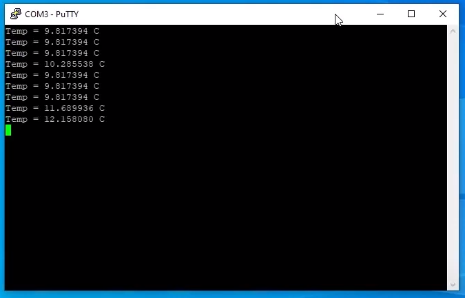
}And there we have it! You can compile your project and should be seeing the temperature output from the RP2040!
Project Source Code
CMakeLists.txt
cmake_minimum_required(VERSION 3.12)

include(pico_sdk_import.cmake)

project(pico-multicore)

pico_sdk_init()

add_executable(multicore
        multicore.c
)

target_link_libraries(multicore
        pico_multicore
        pico_stdlib
        hardware_adc
)

pico_enable_stdio_usb(multicore 1)
pico_enable_stdio_uart(multicore 0)

pico_add_extra_outputs(multicore)
multicore.c
#include <stdio.h>
#include "pico/stdlib.h"
#include "pico/multicore.h"
#include "hardware/irq.h"
#include "hardware/adc.h"

// Core 1 interrupt Handler
void core1_interrupt_handler() {

    // Receive Raw Value, Convert and Print Temperature Value
    while (multicore_fifo_rvalid()){
        uint16_t raw = multicore_fifo_pop_blocking();
        const float conversion_factor = 3.3f / (1 << 12);
        float result = raw * conversion_factor;
        float temp = 27 - (result - 0.706)/0.001721;
        printf("Temp = %f C\n", temp);
    }

    multicore_fifo_clear_irq(); // Clear interrupt
}

// Core 1 Main Code
void core1_entry() {
    // Configure Core 1 Interrupt
    multicore_fifo_clear_irq();
    irq_set_exclusive_handler(SIO_IRQ_PROC1, core1_interrupt_handler);

    irq_set_enabled(SIO_IRQ_PROC1, true);

    // Infinte While Loop to wait for interrupt
    while (1){
        tight_loop_contents();
    }
}

// Core 0 Main Code
int main(void){
    stdio_init_all();

    multicore_launch_core1(core1_entry); // Start core 1 - Do this before any interrupt configuration

    // Configure the ADC
    adc_init();
    adc_set_temp_sensor_enabled(true); // Enable on board temp sensor
    adc_select_input(4);

    // Primary Core 0 Loop
    while (1) {
        uint16_t raw = adc_read();
        multicore_fifo_push_blocking(raw);
        sleep_ms(1000);
    }
}
Thanks for the posting. Maybe, you could convert Celsius to Fahrenheit on Core1 and pass back the Fahrenheit value to Core0 as a example of passing info back.
I took your code and made the main (Core0) do the Celsius conversion and print it from Core0. I broke the celsius value apart into 2 integers and passed them via fifo. In Core1, I read the 2 integers, put them back together, and converted it to Fahrenheit and printed it from Core1.
#include
#include “pico/stdlib.h”
#include “pico/multicore.h”
#include “hardware/irq.h”
#include “hardware/adc.h”
// Core 1 interrupt Handler
void core1_interrupt_handler() {
// Receive Raw Value, Convert and Print Temperature Value
while (multicore_fifo_rvalid()){
uint16_t intpart = multicore_fifo_pop_blocking();
uint16_t decpart = multicore_fifo_pop_blocking();
float raw = intpart + (decpart / 1000.0);
float far_temp = raw * 1.8 + 32;
printf(“Core 1: Temp = %f F\n”, far_temp);
}
multicore_fifo_clear_irq(); // Clear interrupt
}
// Core 1 Main Code
void core1_entry() {
// Configure Core 1 Interrupt
multicore_fifo_clear_irq();
irq_set_exclusive_handler(SIO_IRQ_PROC1, core1_interrupt_handler);
irq_set_enabled(SIO_IRQ_PROC1, true);
// Infinte While Loop to wait for interrupt
while (1){
tight_loop_contents();
}
}
// Core 0 Main Code
int main(void){
stdio_init_all();
multicore_launch_core1(core1_entry); // Start core 1 – Do this before any interrupt configuration
// Configure the ADC
adc_init();
adc_set_temp_sensor_enabled(true); // Enable on board temp sensor
adc_select_input(4);
// Primary Core 0 Loop
while (1) {
uint16_t raw = adc_read();
const float conversion_factor = 3.3f / (1 << 12);
float result = raw * conversion_factor;
float temp = 27 – (result – 0.706)/0.001721;
uint16_t intpart = (uint16_t) temp;
uint16_t decpart = (temp – intpart) * 1000;
printf("Core 0: Temp = %f C\n", temp);
multicore_fifo_push_blocking(intpart);
multicore_fifo_push_blocking(decpart);
sleep_ms(1000);
}
}
Thanks for the article.
I try to use multicore setup, core0 gets commands from USB and core1 execute them.
Unfortunately when I need timing and trying to use sleep_ms() in the core1_interrupt_handler() then *** PANIC *** occurs with this message:
“Attempted to sleep inside of an exception handler; use busy_wait if you must”
What should I do?
Will it work if I change the core0 and core1 tasks?
Thanks is advance.
I’v made a delay function and it works now.