
Introduction
This tutorial will teach you how to use the RGB LED on the Arduino Nano RP2040 Connect. We will walk you through how to create three different sketches using the Arduino IDE which will:
- Alternate the LED colour
- Pulse the blue LED
- Create a rainbow effect to fade between colours
You can find the final source code and the video tutorial is available here (or embedded at the bottom of this page).
Background
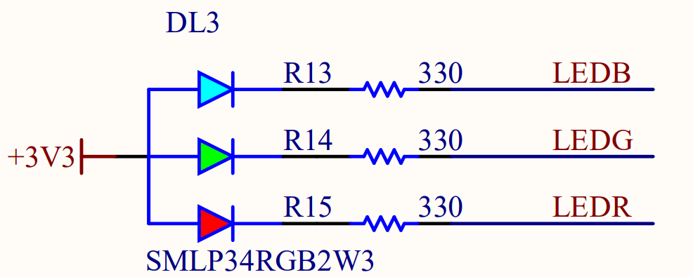
The Arduino Nano RP2040 Connect has an onboard RGB LED which is what is known as a ‘common anode’ LED. We can see that the RGB LED is simply three separate LEDs that are all connected to the same power source on their anode, or positive side, and their negative sides are connected to a corresponding LED label LED B, G and R signifying their colours:
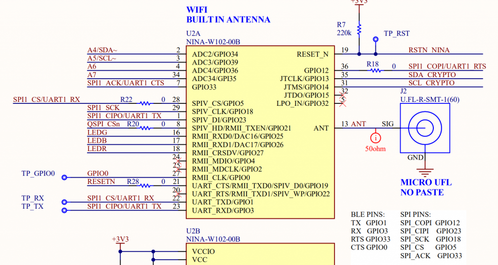
If we have a look at where these labels are actually connected too, we can see they are connected to pins 16 to 18 on the UBlox NINA Module. So in order to use the RGB LED, we are going to have to go through this WiFi module. Fortunately, this is quite easy and a library already exists for us to use this.
Required Libraries
To install these libraries in the Arduino IDE go to Sketch > Include Libraries > Manage Libraries then in the window that opens search for, and install, the following library:
- WiFiNINA
It may take a couple of minutes to download and install this library but once it is completed you can close that window and you are ready to start writing code!
Basic Blink Program
The basic blink program demonstrates simply how to switch the colour of the LED to flash in a binary fashion. This kind of program is equivalent to the blinking the green LED on the Raspberry Pi Pico which was discussed in this tutorial.
The first task is to include the required WiFiNINA header file and we do that using the following line of code:
#include <WiFiNINA.h>With that done, the next stage is to wire the setup function which runs once at the start of the program execution. This function will simply set the each of the red, green and blue pins as outputs by using the pinMode function as follows:
void setup() {
  // Set LED Pins as Outputs
  pinMode(LEDR, OUTPUT);
  pinMode(LEDG, OUTPUT);
  pinMode(LEDB, OUTPUT);
}
Now we can write the primary function (loop) which will run over and over as the program runs. This code simply uses the digitalWrite function to toggle the LED on then off before switching a different LED colour on and then off and so on. The delay function is used to implement a delay of 250ms between turning the LED on and then off again.
void loop() {
  // Cycle Colour Blinking
  digitalWrite(LEDR,HIGH); // Turn On RED LED
  delay(250);
  digitalWrite(LEDR,LOW); // Turn Off RED LED

  digitalWrite(LEDG,HIGH); // Turn On GREEN LED
  delay(250);
  digitalWrite(LEDG,LOW); // Turn Off GREEN LED

  digitalWrite(LEDB,HIGH); // Turn On BLUE LED
  delay(250);
  digitalWrite(LEDB,LOW); // Turn Off BLUE LED
}
Pulsing LED
This sketch will pulse the blue LED on and off creating a nice ‘standby’ effect. This sketch is set up in the same manner as the previous sketch however this time we need to define some varables which will help us keep track of the current state of the brightness of the LED and whether it should be increasing or decreasing. These variables are rgbBlue which stores the blue brightness value and dir which is either 1 or -1 indicating an increasing or decreasing brightness level.
int rgbBlue = 0, dir=1;The main changes are found withing the loop function. Firstly, as we want to fade the LED and not just turn it 100% on or 100% off, we use the analogWrite function instead of the digitalWrite. This allows us to write a value between 0 and 255 to the corrosponding pin (or LED colour) . This actually adjusts the PWM duty cycle applied on that pin. The rest of the code simply iterates the brightness either upwards or downwards depending on the current brightness direction. The if statements enable the direction change once rgbBlue has reached either of its limits (0 or 255).
Confusingly a duty cycle of zero actually means that the LED is at it’s brightest and when 255, the LED is disabled. This is because the RGB LED has a common anode meaning that that when the duty cycle is zero, a potential difference across the LED occurs and the LED can light up. When at 100 percent duty cycle, no current can flow through the LED.
void loop() {
  // put your main code here, to run repeatedly:
  rgbBlue = rgbBlue + (1 * dir);

  if(rgbBlue > 255){
    rgbBlue = 255;
    dir = -1;
  }

   if(rgbBlue < 0){
    rgbBlue = 0;
    dir = 1;
  }
  analogWrite(LEDB, rgbBlue);
  delay(5);
}
Rainbow Fading RGB LED
The final part of this tutorial is creating an impressive fade or rainbow effect between the red, green and blue primary colours. It will constantly cycle through the RGB colours whilst mixing two colours together. For example, as the intensity of the red LED decreases, the intensity of the blue LED increases and then the blue LED decreases whilst green gets brighter and so on.
To start with, we are going to setup the code exactly like the others by including the WiFiNINA library and setting the RGB pins as outputs. We are then going to define some integer variables. First is going to be an array of three values which correspond to the RGB values at any given iteration of the loop. The first number is red, the second is blue and the third is green. We are going to start the loop with red at it’s maximum value and green and blue at their lowest. This is inverse to what we said earlier but I deal with that later.
Then we need two variables to track which colour is increasing and which one is decreasing, and I have called these variables up and down index. In this case I will indicate that the Blue LED is about to increase it’s value by setting the upIndex of the rgbValues array to one. I will say that red is going to decrease.
#include <WiFiNINA.h>

int rgbValues[] = {255, 0, 0}; // 0=Red, 1=Green and 2=Blue
int upIndex=0, downIndex=1;

void setup() {
  // Set the RGB pins to output
  pinMode(LEDR, OUTPUT);
  pinMode(LEDG, OUTPUT);
  pinMode(LEDB, OUTPUT);
}
Now that’s all the setup that we need to do, moving into the main loop we need to increase the value of the RGB value which is increasing and decreasing the one that is decreasing. We can do this by these two lines of code here and this is executed each time the program loops.
Then we need two if statements which essentially switch the colour which is being increased and the one that is being decreased. Say for example that red is increasing, once it reaches it’s maximum value it should stop increasing and then the green LED should start increasing. We create an if statement which simply iterates the colour index once the intensity reaches it’s maximum. Another IF statement is used to wrap the index back to zero (or red) after it switches through blue. We repeat a similar IF statement for the decreasing LED index.
Finally, we use the analogue write function to set the LED value each main loop iteration. In the value we use 255 – the current value of each LED and this is because the RGB LEDs are a common anode so when the analogue value is 255, the LED is actually at it’s lowest intensity. So this essentially flips the working out that we previously did. If the LEDs that you were using were common cathode then you wouldn’t need to do the 255 minus the LED value, you would just do set each LED value. Then a short delay of five milliseconds to allow for smooth fading is added! You can now build and upload your sketch and you should see some nice LED rainbow fading.
void loop() {
  rgbValues[upIndex] += 1;
  rgbValues[downIndex] -= 1;

  if(rgbValues[upIndex] > 255){
    rgbValues[upIndex] = 255;
    upIndex = upIndex + 1;

    if(upIndex > 2){
      upIndex = 0;
    }
  }

  if(rgbValues[downIndex] < 0){
    rgbValues[downIndex] = 0;
    downIndex = downIndex + 1;

    if(downIndex > 2){
      downIndex = 0;
    }
  }

  analogWrite(LEDR, 255 - rgbValues[0]);
  analogWrite(LEDG, 255 - rgbValues[1]);
  analogWrite(LEDB, 255 - rgbValues[2]);

  delay(5);
}
Source Code
Blinky
#include <WiFiNINA.h>

void setup() {
  // Set LED Pins as Outputs
  pinMode(LEDR, OUTPUT);
  pinMode(LEDG, OUTPUT);
  pinMode(LEDB, OUTPUT);
}

void loop() {
  // Cycle Colour Blinking
  digitalWrite(LEDR,HIGH); // Turn On RED LED
  delay(250);
  digitalWrite(LEDR,LOW); // Turn Off RED LED

  digitalWrite(LEDG,HIGH); // Turn On GREEN LED
  delay(250);
  digitalWrite(LEDG,LOW); // Turn Off GREEN LED

  digitalWrite(LEDB,HIGH); // Turn On BLUE LED
  delay(250);
  digitalWrite(LEDB,LOW); // Turn Off BLUE LED
}
Pulsing/Fading LED
#include <WiFiNINA.h>

int rgbBlue = 0, dir=1;

void setup() {
  // Set the LED pins as outputs
  pinMode(LEDB, OUTPUT);
}

void loop() {
  // put your main code here, to run repeatedly:
  rgbBlue = rgbBlue + (1 * dir);

  if(rgbBlue > 255){
    rgbBlue = 255;
    dir = -1;
  }

   if(rgbBlue < 0){
    rgbBlue = 0;
    dir = 1;
  }
  analogWrite(LEDB, rgbBlue);
  delay(5);
}
Rainbow LED
#include <WiFiNINA.h>

int rgbValues[] = {255, 0, 0}; // 0=Red, 1=Green and 2=Blue
int upIndex=0, downIndex=1;

void setup() {
  // Set the RGB pins to output
  pinMode(LEDR, OUTPUT);
  pinMode(LEDG, OUTPUT);
  pinMode(LEDB, OUTPUT);
}

void loop() {
  rgbValues[upIndex] += 1;
  rgbValues[downIndex] -= 1;

  if(rgbValues[upIndex] > 255){
    rgbValues[upIndex] = 255;
    upIndex = upIndex + 1;

    if(upIndex > 2){
      upIndex = 0;
    }
  }

  if(rgbValues[downIndex] < 0){
    rgbValues[downIndex] = 0;
    downIndex = downIndex + 1;

    if(downIndex > 2){
      downIndex = 0;
    }
  }

  analogWrite(LEDR, 255 - rgbValues[0]);
  analogWrite(LEDG, 255 - rgbValues[1]);
  analogWrite(LEDB, 255 - rgbValues[2]);

  delay(5);
}